You're viewing an archived page. It is no longer being updated.
Installation Instructions for GroupD Dell Test-boxes
The Test Traffic Measurement Service (TTM) was shut down on 1 July 2014. This information is available for historical reference.
0. Open the package(s) and see what you have
You must have the articles below.
- A test-box installed on a Dell PowerEdge 350 with standard accessories
- A short serial-to-serial cable
- Dell manuals and original accessories, including European power cord and one black Dell front cover
- Dell rack rails with original documentation
- A white Trimble Acutime2000 GPS antenna
- GPS antenna-to-DB25 cable (weather-resistant except the DB25 connector)
- DB25-to-UTP cable
- UTP-to-UTP connector (small, light grey rectangular box)
- An antenna ratchet mount with adjustable brackets
1. Arranging the Antenna and Cabling
A good view of satellites and a precise time resolution are the essentials. For your GPS antenna, find a place that has the largest possible clear view of the sky. While choosing that place, keep in mind that you can use up to 300 meters of cat5 UTP cable in the building to reach the test-box.
- Attach the antenna mounting to a suitable place. Remember that you may need to adjust the antenna position anytime. So, do not forget to leave a certain degree of freedom for its movements. The antenna, the 12-pin black connector, and the black cable is weather-resistant but not the DB25 connector at the other end.
- Screw in the antenna and adjust the ratchet towards the largest possible clear view of the sky.
- Connect the cable to the back of the antenna.
- Take the DB25 end of the cable inside the building.
- Attach the DB25-to-UTP cable. If this is not enough to reach the test-box, use the UTP-to-UTP connector and extend it with a maximum of 300 meters of standard cat5 UTP cable.
NOTE 1: Do not use your existing active and/or intelligent cable switching network in the building. You may safely use existing cat5 UTP wiring through mechanical patch panels but active switching equipment would not survive the +30 V DC from the test-box to the antenna. Mechanical routing has been tested to work up to 300 meters. If you have some neighbours testing radar equipment in the next building, your mileage may vary.
NOTE 2: If you use cable other than CAT5, do not extend the unused outputs from the Trimble (pins 6 and 7, and 8 and 10, respectively). This has given interference problems in the past.
Also connect the two serial ports on the back of the Test-box with a short serial cable.
2. Installing the Test-box
The test-box will not be directly accessible by the host and should be directly reachable via network once booted. You may anyway need some access for local maintenance. This would be done by:
- Plugging in a standard keyboard and a VGA monitor on the back of the testbox
- Attaching a serial console to the serial port on the FRONT (using a Cisco-like console cable) if you just need the console output and emergency console access (check appendix for details)
Please note that none of the above should be needed in absence of troubles. 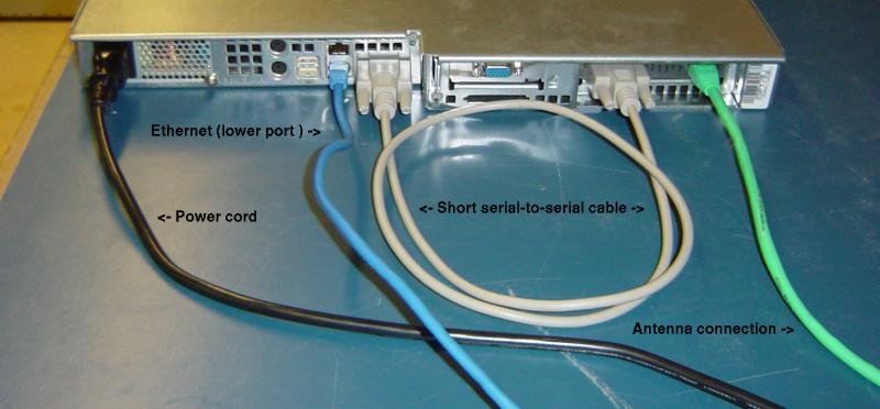
Connections check-list:
- Short serial-to-serial cable:
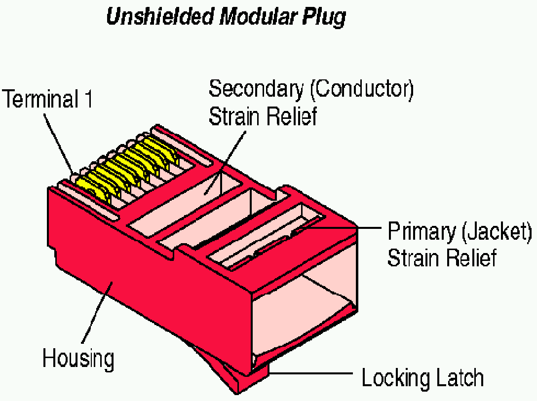
At the back of the test-box you will find two DB9 connectors. One is on the antenna interfacing card (black female, near four LEDs named 30V, 5V, GPS, PPS) and the other is on the middle (male). Connect them together with the supplied short serial-to-serial cable. - Antenna connection:
The RJ45 connector near the serial port at the other side of the LEDs is for the UTP cable coming from the antenna. It has nothing to do with any kind of Ethernet except using the same connector type. This is not a design flaw but a choice to allow you to easily make your own custom length antenna cables. Attach it. Label the cable and port (e.g. "NON-ETHERNET", "DO NOT CONNECT ETHERNET") according to your needs. - Ethernet:
The two RJ45 connectors on the left are the Ethernet ports. Attach the network cable from your LAN to the bottom one.
Dell test-boxes are bare when they are out of the package and some buttons are seen on the front panel. Before attaching the front panel cover, examine the available buttons. Since they are little microswitches under a plastic sheet, they may not seem like buttons at all. 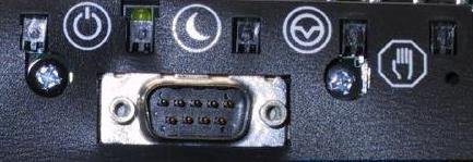
The buttons, in order from left to right are power, stand-by/sleep, reset and halt. The DB9 connector seen in the picture is the COM2/serial console port. Attaching the front cover makes all inaccessible. So keep the cover attached if possible.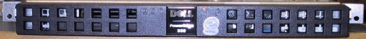
When all connections are done, power on the test-box. Wait a reasonable time to boot if you do not watch it booting. It should come up with the network parameters that you gave us in your application form. Try pinging the test-box from several hosts. If you cannot, check your firewall parameters and other related configuration. If everything goes well, send us an e-mail to tt-ops@ripe.net. If you need further help, please do not hesitate to contact us.
Appendix A
How to attach a serial console
If you want to connect a serial console:
- You will need either a null-modem cable or a standard serial cable and a null-modem adapter.
- The console output goes to COM2 in the FRONT of the test-box.
- The serial parameters for the console are: 9600, 8N1, CTS/RTS (hardware flow control).
- Both keyboard and mouse MUST be already disconnected during bootup in order for the console port to be active.
- The BIOS output, the FreeBSD kernel boot process, plus an emergency login prompt are made available at the console port.
Appendix B
How to interpret the LEDs on the antenna interfacing card
There are four LEDs, all green, on the antenna interfacing card. They are labeled as 30V, 5V, GPS, PPS.
- 30V : This is directly connected to the 30V supply output of the card. 30V DC is supplied to power the antenna. Must be lit on normal operation.
- 5V : This is directly connected to the 5V supply used internally by the antenna interfacing card. Must be lit on normal operation.
- GPS : This LED flashes whenever a tranmission happens from the antenna to the antenna interfacing card. If this LED NEVER flashes, you are likely to have some problems.
- PPS : When enough satellites are seen and a time resolution is achieved, the antenna sends 1 Hz. (i.e. one pulse/second) square wave to the interfacing card. You can watch this on PPS LED after antenna starts time resolution (i.e. within 1 hour after power up). If this does not happen, it is most likely that your antenna does not see enough satellites or you have some serious cabling problems.